Well,
After completing Part II, I thought I was well on my way to completing this SB-200 project. Well, I should say, ‘complete enough’ of the project, because Heathkits are never complete- the projects hang out in the 95% area of completion, as there is always a mod or 3 that you could do to squeak out a few more watts. I was shooting for the 90%, get the amp to push RF and get the amp on the air. Adjusting the tuning coils and tweaking this and that could come later- I wanted to see the needle on the Bird 43 meter start moving!
I was at the point where I needed to hook up the radio and do the final RF testing, following the steps in the SB-200_Manual starting on page 44.
- Connect the amplifier to the exciter and the antenna. Do not turn the Linear Amplifier ON, thus permitting the exciter to feed through the Linear Amplifier to the antenna.
- Place the Linear Amplifier Meter switch in the REF PWR position.
- Load the excited to full output. The meter of the Linear Amplifier may be used for this purpose, as it will function in both the REL PWR and SWR positions without the Linear Amplifier being turned ON.
- Adjust the REL PWR SENS control of the Linear Amplifier for a SET (full-scale) indication on the meter.
- Turn the meter switch to SWR and read the standing wave ratio directioly from the meter (1 to 3 scale).
All seemed simple enough yes?
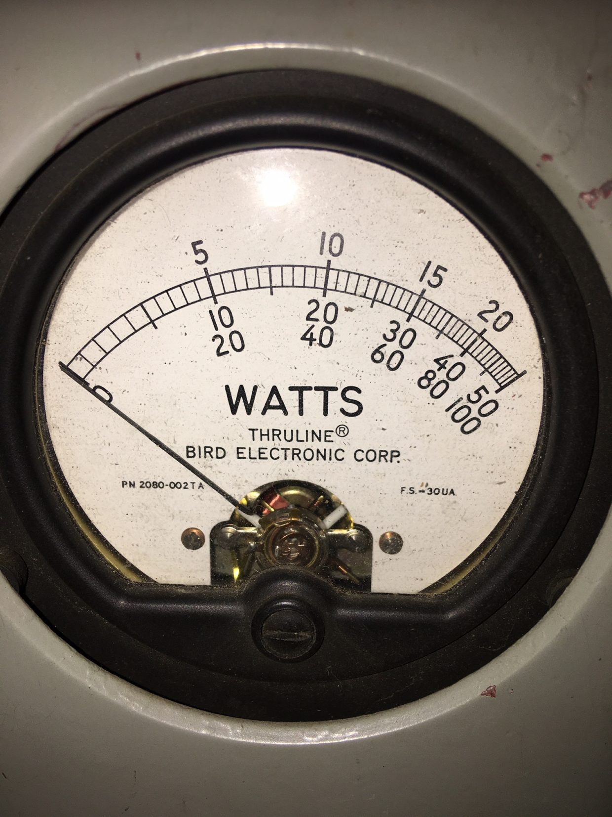
I connected the radio to the input of the amp, the output of the amp going into the Bird 43 meter, then out of the meter going into my MFJ-250 dummy load. (Speaking of which, does everyone of these leak the mineral oil back on to the top of the can from the SO-239 antenna jack mounted in the middle of the lid? What a FREAKING MESS!)
Well, I get everything connected and hit the CW key on the radio. The SWR meter on the radio pegs on high SWR. and <high SWR> flashed on the radio. Humm.. that is not good. I check the cables and do it again for the same result. I disconnect the amplifier so I am going from the radio – Bird – dummy load. Transmit.
Flat SWR on 80m – 10m. Hummmmmmmm…
I set everything back to put the amp in line. Try it again. Again, the SWR meter on the radio pegs on high SWR. and <high SWR> flashed on the radio. This isn’t the way it should be.
I flip on the amp and key the amp using my foot switch.
‘CLACK’
I hear the relay engage.
I hit it and release several more times.
‘CLACK’ ‘CLACK’ ‘CLACK’
I hit the key on my radio to put out a steady carrier…
‘sizzzle sizzle sizzle’
replied the amp from some region around the tubes. SH*T !!!
Something was not right. I stopped keying after about 2 seconds and shut off the amp.
Watching the HV bleed down on the meter, I try to transmit again as the directions state. This time, RF passes through the amp for about 2 second, then the SWR pegs on the radio.
“Hello Google…” as my fingers start typing on my phone looking for answers.
Withing a few minutes, I come to see that this is a common issue when the relay is bad in the amp. DAMN. There are steps to clean it, but, again, with the unknown history of this amp, why bother. I opened the case to look at it, and compared to the other relays I have seen in some of the amps, this one looked ‘cleanish’.
Looks can be deceiving. Make sure to test everything with a meter.
However, looks can be deceiving. Always have to look and then test with the meter. Pushing and probing around the meter, I could see that it was not working as it should. Time to order another part from Harbach, this time the relay and replacement resistor. Fifteen minutes later, the RY-200 was ordered. Progress would be halted for a few weeks due to a trip back east the following weekend.
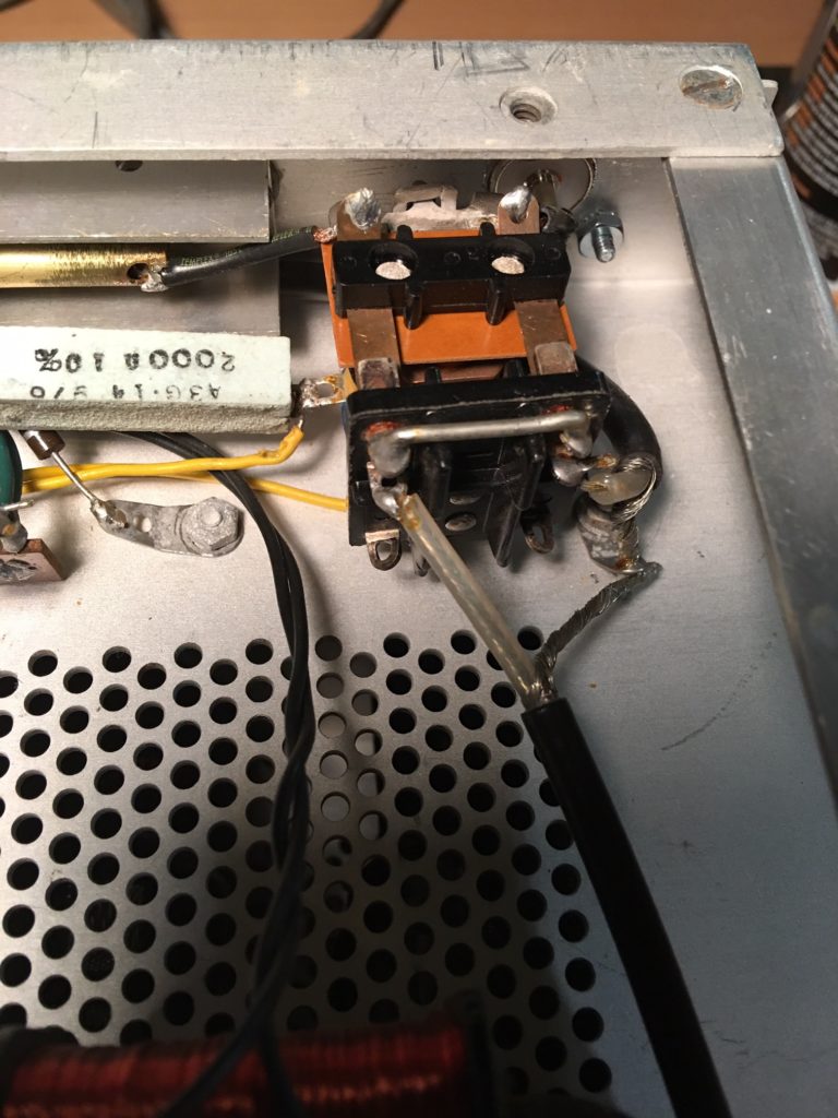
After few weeks I had some time and I went back out to the the garage to work on the amp. I took about a dozen pictures of how everything was connected on the old relay, and then pulled it out, as well as the 2000 Ohm resistor, As the new relay has a new 4.7K 5W R-18 replacement. This resistor replaces the original R-18 (2K 7W). This resistor is changed due to a change in coil resistance of the relay from about 2.3K to 1.4K by the relay manufacturer. This will allow the proper amount of operating bias to be applied to the tubes during transmit (~ -2VDC).
I swapped out both the relay and the resistor, then went about connecting everything back up. About 50 minutes later, I had the case on and was back to the point I was a week ago with the radio and dummy load hooked up.
With the amp off I keyed the radio.
NO high SWR! Wahoo!
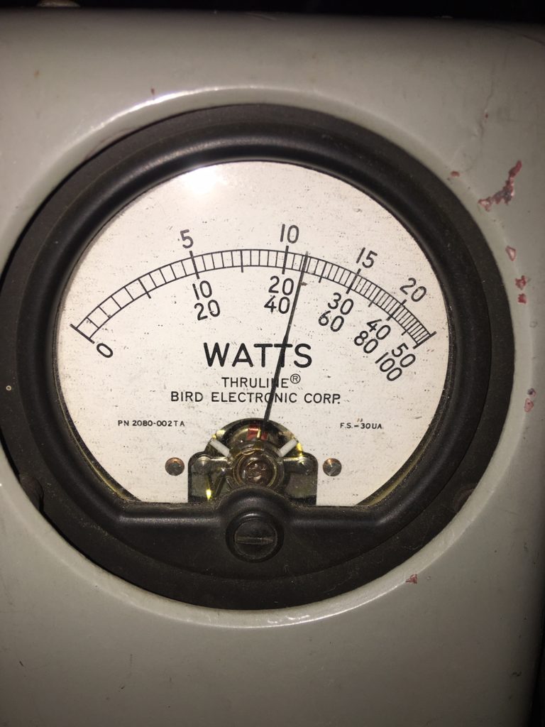
I can see the needle of the meter on the SB-200 moving about as well. Wahoo!
I quickly went through the steps in the manual and then fired up the amp. Again, keying the amp with the foot switch, I was able to use my key to put out a steady carrier and I adjusted the plate. ‘DIP the PLATE!’ I started out at 40W of carrier on 20m and started fiddling with the amplifier. Adjust the TUNE to the point where the plate voltage dips, while watching the meter on the SB-200, then quickly move to the LOAD adjustment and tune for max power, while observing the meter on the Bird 43 move. Unkey the amp after about 5 seconds and do it again, however this time more granular on the TUNE and LOAD adjustments.
Dip the plate with the TUNE knob, then adjust the LOAD for max power out – 450w on 1000W slug.
I did this for about the next 20 minutes on all the bands, first at 40w, then again at 60w. Ninety nine percent of what I have read in the forums and mail lists state that you do not need to run more than 60W of power to get the 10dB gain that this amp should provide. Sixty watts in should net 600W out, in theory. Sure, I could crank it up to 100W into the amp, but I bet I would be splattering all over the place when I get it off the dummy load and on the air.
So, with 60 watts, this was my net result, with the tubes that came with the amplifier.
Wired for 120V.
HV at rest 2300V
key down 1800V (and yes, the lights were dimming)
80 meters: 400W
40 meters: 560W
20 meters: 500W
15 meters: 440W
10 meters: 300W
I am delighted with those results. I discovered for myself how touchy the adjustments are for 10M. Everyone online talk about this issue, and it is true. Very small movements make drastic changes. I might have to do something about that. (And now we are into the 95% I spoke about earlier…) I was surprised 80 and 40 meters were not higher, but that could be the voltage drop, the age of the tubes, or even some resistors out of spec. However, for now I am excited. The magic smoke stayed in the rig, no funny smells, and it works as it should (or close) and I think the next step is getting it on the air. Wahoo!
Beyond the adjustment for 10m and some research on the 40 and 80m ‘low’ power, I want to add a muffin fan to the amplifier to help with cooling. (Again… back to 95%). Excited to get it on the air for some tests. I might have to reach out to Steve, KD1O back in Maine for some honest signal reports.
David Anderson January 1, 2023
OM, as I’m trying to resurect an SB-200 hanger queen, I found that I too need an antenna relay. Unfortunatly, Harbaugh is out of stock and doesn’t have a source for replacement parts. Are you aware of an alternate source? Otherwise it’s good ‘ole eBay.
N1AV January 1, 2023 — Post Author
Sorry David, I am not aware of any.
Robert Klaus December 7, 2021
I enjoyed reading the series, what’s the amp. doing with the new tubes? What else have you done, hows it working Now in Dec. 2021?
N1AV December 7, 2021 — Post Author
Thanks!
The new tubes work well in this amp. I only drive it 300 to 600w depending on the band. It delivers much more power on 40 and 80m than 10 or 15.
Overall I need to tweak the input tuning slugs to drop the SWR on several of the bands but it does work.