About a year ago I decided that I wanted big power on 6M, as I wanted to be able to work some of the marginal stations I was able to hear during some of the openings. Well, to be honest I wanted an amp for 6M after my first sporadic E season back in Maine.. but, I could actually dedicate funds to one and the time/energy/knowledge to make it all work in the past few years. You know those situations, where you can hear those DX stations calling CQ, you answer.. and they still call CQ.. and you answer.. and they still call CQ.. back and forth, back and forth, until they fade out.
So, having another 10dB of signal should at least get their attention!
The Harris Platinum RF decks are surplus analog TV transmission amplifiers. A lot has been written about them by Lance, W7GJ, at his site. There is also information about there here. KL7UW also has a page about his Harris Platinum deck. Needless to say, I am not attempting anything new here, just standing on the shoulders of giants to use their work to get this up and running. They will do 700-1000 watts output with 6-10 watts input. Very low drive is needed. Using my FT817 as a test platform, 1 watt in was making about 70 watts out, and 5W from the 817 was producing about 370W into a dummy load. Cool!
Most of these guys (I mentioned above) are taking two of these RF decks, combining their output and running each of them at lower power around 700-750W output power, for a full 1500 watts on 6M. A single deck when pushed can approach that power out by itself, but starts to put stress on the components. Replacements (outside of buying a whole new deck) are made of “unobtanium”, as in, you can’t get replacement parts. My plan (at this point) is to just run 1 deck at about 1000W, which I think will allow me to work who I want. If I want to get crazy and start thinking about EME on 6M, then I might have to pull the backup deck I have (yes, I got a spare as well) and get that into the mix.
Cooling
One of the big killers of these decks is the heat they generate. They can overheat quickly if you do not keep them cool. You have to keep these decks cool with a lot of air, as in multiple fans. Relying just on the heat sink means you will smoke the amp, a lot of folks have done this. The heat sink cannot keep up with the cooling needs of the deck. Lance’s site talks about this, as well as other sites and numerous emails on various lists, you HAVE to keep these cool for them to perform in the long term- and I would really like to not have to replace this anytime soon. So, I needed to build a fan manifold for the heat sink, as illustrated by Lance and others.
Let it be known, I am NOT a engineer. Not even close. My vocabulary does not include the word “perfect” or “exact”. Rather, I utter the phrase “close enough” a great deal. Folks would classify a lot of my projects as 90% done, 100% functional. I get it working, but not exactly (or even close to) to the standards of others. My lines are not perfect, stuff isn’t exactly straight, but it works, and stations are in the log! That is ALL I care about since this deck is going to be stuffed away in a server rack and no one is going to be inspecting or reviewing it for build or style points.
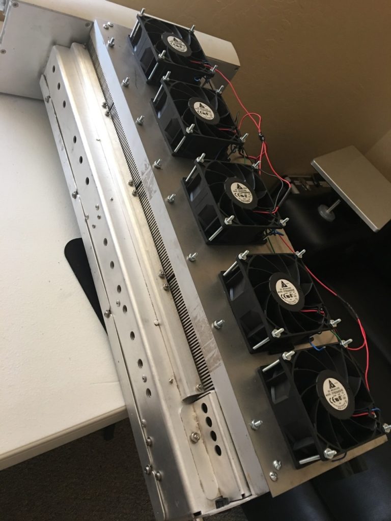
The manifold is nothing more than a “tight fitting shelf” that sits on top of the heat sink to hold the fans and associated wiring, as well as forces air up through the deck. My first step was to lay out the fans to get an idea of the rough measurements of where they would be located on each of the heat sink blocks.
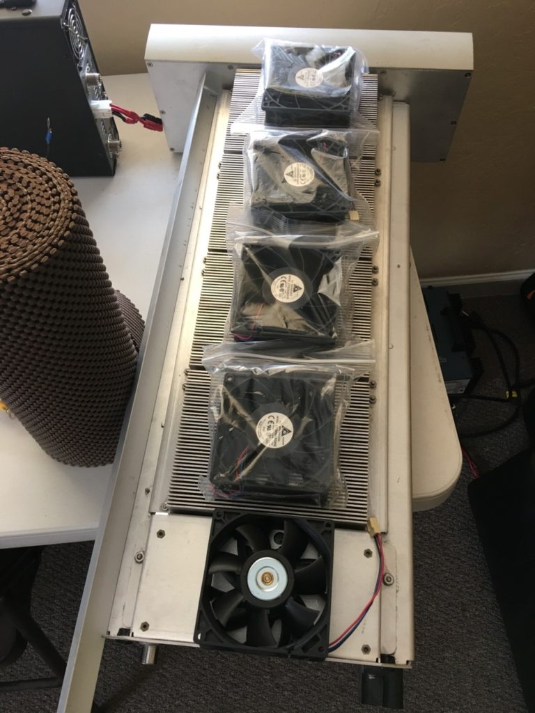
Image of the deck with the fans placed on the amp so I have a rough idea of what they will sit, including one for the control module at the back of the deck.
For my fans, I used the same 48 volt fans as discussed in the links I included in the start of this post. They are 48V, so they will work off the same HV supply as the RF deck, and they move a large amount of air. One fan for each heat sink block and one for the control module at the back of the amp was the plan. Once I had the fans laid out, I build the frame out of 1″ aluminum angle iron and sheet metal for the top all from the local hardware store. I then traced out the fan locations and started cutting them out with the dremel tool, and burned through about a dozen ‘cut off wheels’ in the process.
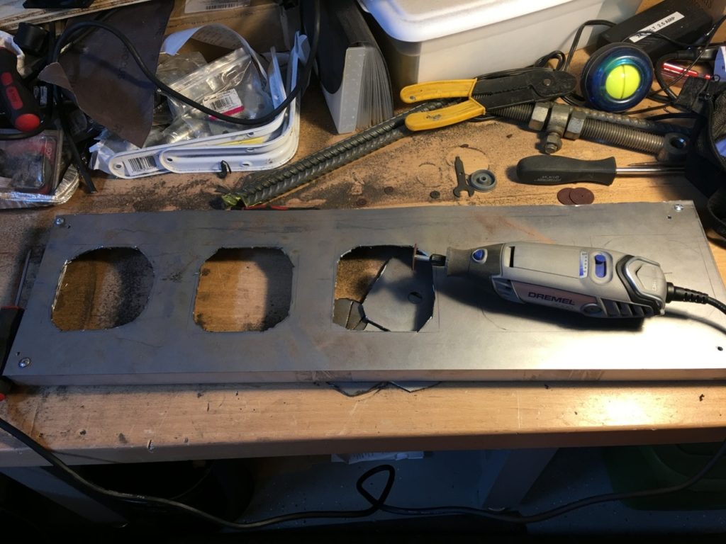
A lot of cutting wheels died in the quest to complete this project. The dremel is one of my favorite building tools. Crude but works!
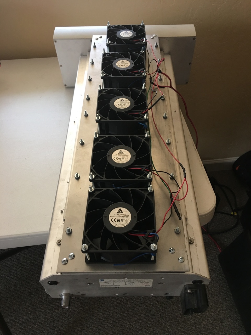
Once all the cutting was complete, it was time to get the fans mounted and bolted into place. I used #6 2″ bolts for the fans, and #6 1/2″ for the frame of the manifold.
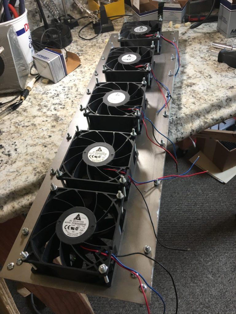
Not even close to being straight.. but at least I got them all sucking air OUT, and the wiring is all on the same side. 😉
From there, I did some last minute touch ups of any ‘hanging chads’ of aluminum and made sure the holes were open enough for the fans. I could have gone a bit wider on some, but I think I am OK. If I notice the external temp gauge climbing high (a cheap automotive temperature gauge that I lay in the heat sink fins), I can go back and open them up some more. I did notice the placement of the last fan was a bit tight to the frame and had to make some minor adjustments..oh well.. you will never see it anyway.
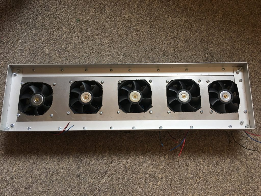
Placed on the RF deck ready for testing!
All wired up and ready for testing.
It is important that I get good airflow not only away from the heat sink, but air movement into the heat sink and the control module on the back from the holes on the side of the deck. When I tested this fan layout I could feel the air being pulled into the amp as well, so I think I will be good there.
Five 48V fans all running at 51V make some noise – but having them all in the server rack, and me wearing my Heil headphones, will block most of the noise.
Attenuation
The other issue with these amps is that they are very susceptible to RF spikes on your radio. If your radio puts out more than 10-20W even for a millisecond, you can burn out the amp. This was (and sadly still is) common for some radios. Many folks have picked up this board, got everything good to go, turned down their radio drive to 10W.. and keyed the mic. POOF! Blown out components.. You now have a dead amp.
So what is going on? Well, with some radios, when you key it via the mic or the accessory jack on the back, or the CW key, regardless of what you have the output drive level set to, it will deliver a full power 100W spike of RF for a very short period of time. Some of the older Icom radios were notorious for this, but it isn’t just an Icom issue. In any case, it is not good. Many folks roll the dice and just turn down the drive on their radios so the radio delivers the 8-10W to the amplifier. However, the best solution is to run the radio at full power, and use attenuation to reduce the drive. This guarantees that even a millisecond RF spike will be attenuated by the attenuator that you have inline, and the amp (or transverter, or what ever else is downstream) will be protected.
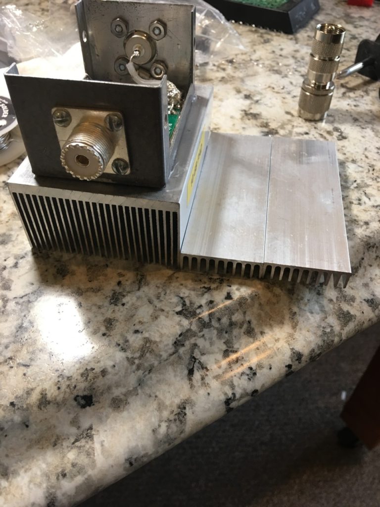
I picked up a W6PQL 6M 100W, 10dB attenuator for this project and have it mounted to the heat sink, wired in a box.
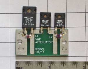
The W6PQL attenuator, before mounting on the heat sink (This is one for 2m)
My plan is to have this attenuator box mounted right at the input of the amplifier, NOT back at the radio, as I am constantly moving feed lines around, and would HATE to disconnect this attenuator, then forget to connect it back up, catch a sweet 6M opening.. and blow the amp. So, it will sit in the amplifier rack with the amp, taking about 50-90W from the radio to give me 5-9 watts out to drive the amp.
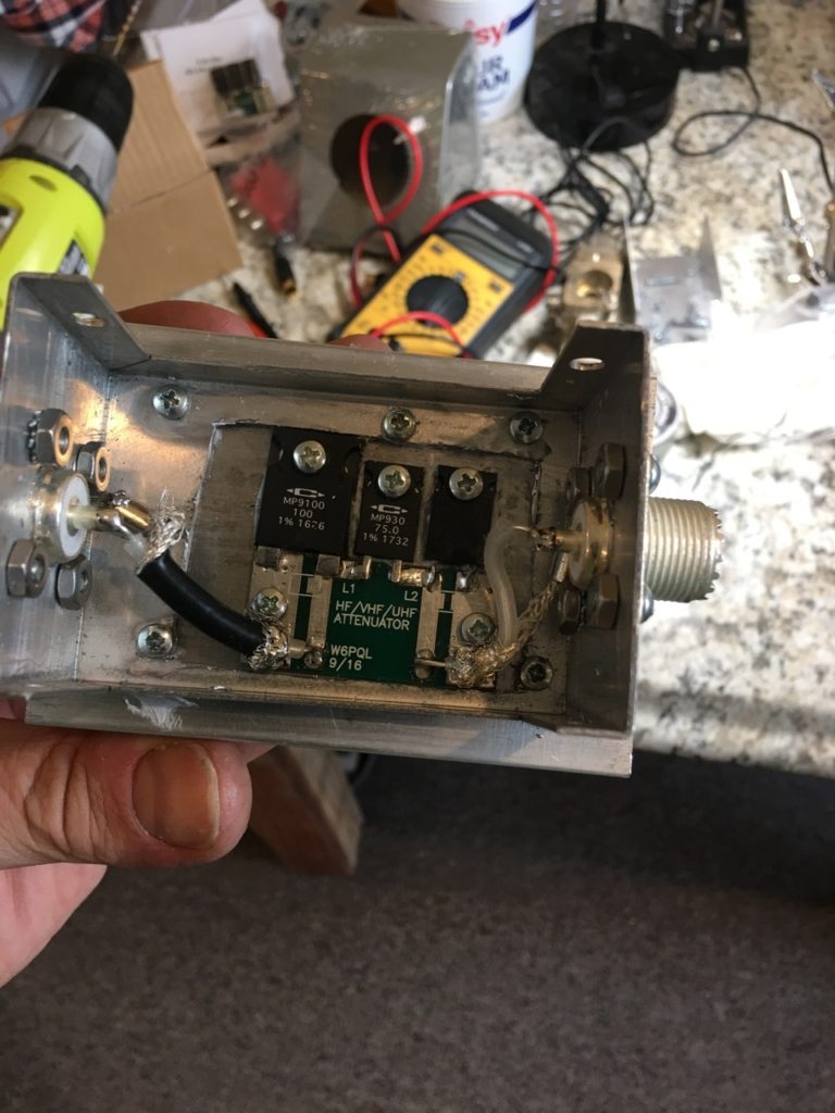
You can see my crude cutting job of hacking the bottom of the box, so I can mount directly to the heat sink, and box added for the coax connections.
I did some testing with a smaller heat sink and found that it just was not working. The resistors were getting VERY hot during transmit at 50W, so I upgraded to a larger heat sink. That change helped quite a bit, in this larger heat sink, the resistor is “hot” but not “burn your finger hot” as before. WIN! Another example of me not being an engineer based upon my temperature measurement standards.
In this project I even got to play with my tap and die set, to drill and tap the holes in the heat sink to mount the resistors for a cleaner more professional job, which was cool – as I never had done that before.
#Handsoneducation
Now I just need to add another fan to blow across the sink to keep it cool – probably a 12V computer processor fan is what I will use- and we should be good!
The old heat sink might get reused for some lower power attenuators, but I wasn’t happy with it for 100W. The upgrade to the larger heat sink was an easy find on Ebay. It’s only money, and I got an education out of it. Bonus!
Next Steps
The next steps will be to get the relays wired up and working with the sequencer I put together, and the 6M RF filter installed, then coax run and control lines for the PTT for the amp and the TXinhibit on the Yaesu radios (I love that Yaesu radios have this feature).
I will cover all of that in my own colorful way in Part II, soon.