In my local ham group several folks have been saying that they can’t put up a big antenna for HOA reasons, or you need big expensive antennas to work people on HF, or they don’t have the room to string a dipole on 40m in their smaller back yards, all reasons why they never get on the HF bands.
I wanted to debunk that line of thinking and decided to make a quick an dirty antenna from start to finish to show it could be done.
Requirements:
- Had to be completely made in the park
- Had to cheap aka under $25
- Had to be able to fit in a small yard
- Had to be created in less than 2 hours
- Had to work on at least two bands
- Had to be simple!
I decided to go with a quarter wave vertical as the antenna. 1/4 wave, on 40 – 10 meters. I choose to make this completely out of ethernet cable. Yes, ethernet cable. You know, that blue or grey cable that you plug into the back of your computer and then into the wall?
This stuff.
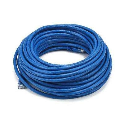
100′ feet of ethernet cable for $19.
I supported the business of one of our local hams, Home Depot, and picked up a 100′ roll of Cat 6 ethernet cable for $19.
This would be all the wire that I will need for this antenna.
YES.. I KNOW.. this wire is SOLID and not stranded.
I know, yup, it might break,
yup.. it will not be durable.. yup.
Got it. I know all of this.
This was a proof of concept.
Can it be done and can it be done cheap?
And.. Can you work anyone with it?
As far as the cable, where are you going to find 800′ of stranded 24 gauge wire for $19? I would have gladly used it.
What.. what? Jay.. you said you got an 100′ length NOT 800′ ?
Correct! CAT5 or CAT6 ethernet cable has 8 different wires running inside of the outer sheath. When you peel back the sheath, it looks like this.
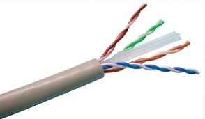
This is the what the inside of an ethernet cable looks like.. 4 pairs of twisted cable.
So.. a 100′ ethernet cable has eight 100′ lengths of solid (23 or 24 gauge) wire in it. That has a lot of possibilities for a temporary, portable, emergency antenna!
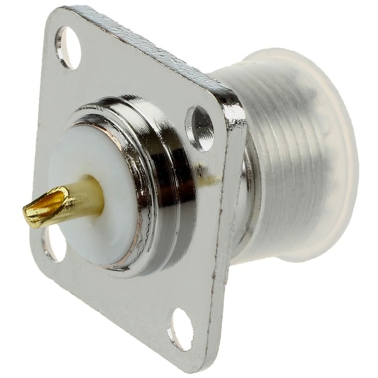
I also had a SO-239 coax connector in the hamfest junk box (We all have one of these right? Those items you pick up at a hamefest and think.. ” I will use that sometime..”), I think I paid a buck for it at the local hamfest.
SO.. all in, about $20 TOTAL for the antenna.
What will I get with this $20? Well, if everything works according to plan, a resonant (aka NO TURNER NEEDED) HF antenna that can cover the following bands with one feedline: 40m, 30m, 20m, 17m, 15m, 12m 10m and 6m as a bonus. All from the same 100′ of cable.
How is this done? I based this design off these two links.
Design
I used these links as the foundation for my antenna plan.
http://www.hamuniverse.com/hc4w4bwsgroundplane.html
http://www.hamuniverse.com/kl7jrmultibandvert4010.html
Both of these designs have all of the vertical radiating elements coming from the center conductor of one connector. So, all the vertical “elements” are all soldered together, and the radials are strung out (as a bundle or separate) for each band.
Assembly
Thinking that this was a “Quick and Dirty Proof of Concept“, I took my 100′ roll of ethernet cable to three equal 33′ lengths. One would be taped to my 31′ jackite pole as the vertical radiator, and the other two would lay on the ground as the radials, one laid out to the east, the other laid out the west. Yes, all the ethernet wires were all still in the sheath and wrapped twisted around each other. I didn’t make any attempt to untwist them.
From there I measured the length that I would need for each band, and opened the sheath to “cut” the designated cable at that length, then would measure out to the next length (such as 16′ 6″ for 20m) and then open the sheath again, find the orange and orange stripe wires based upon my notes, then cut them.
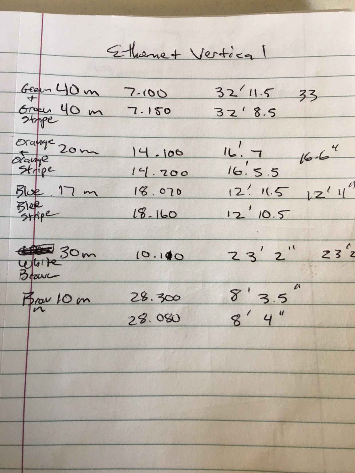
You can see the color code I designed for each band as well as the lengths I used to make a 1/4 wave vertical on 40/30/20/17/10. I used a free app on my iPhone to get the needed lengths, however, the links I posted above also have them included.
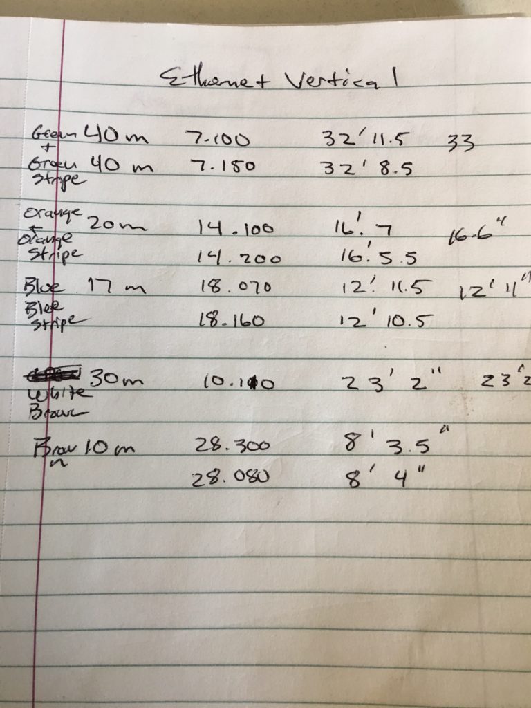
Notes for constructing the ethernet cable vertical
I decided to “double up” on the three bands that I use the most, knowing that the wire was brittle. So for the 40m band I used two stands, as well as two on 20m and then again 2 on 17m. Then a single strand for 30m and 10m, therefore using all 8 wires.
Jay? You said this would work on 15 and 6 too? What wires did you use there?
Great catch! 15m and 6m are multiple wavelengths of 40m. So, I didn’t use any wire for those bands at all, and they should be resonant based upon the 40m vertical.
Once I cut and pruned the antenna for each band I taped the vertical radiator to my 31′ Jackite pole for support with electrical tape and stretched the radials out on the ground. One set to the east, the other set to the west.
The center conductor was soldered to the center pin of the SO-239, and each radial bundle was soldered to one of the 4 mounting screw holes.
Yeah OK Jay.. but you were using a 100W rig with this antenna right? Something with some power?
Nope!
For this trip to the park I was going back 40 years with the radio to prove what you can do with low power and a vertical antenna.
Yaesu FT-7
I was using a “new to me” Yaesu FT-7. Not FT-700, or FT-7000…. Fox Tango – Seven. Yes, that old radio that you used back in the 1980’s. We are talking a 1976 production date radio. No DSP, basic functionality, analog display HF radio.
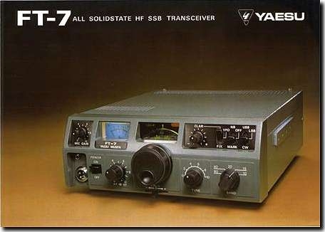
The FT-7 is a very basic, non threatening, old school Yaesu HF rig, covering only the 80-40-20-15-10 bands. 10m is the high side, 28.5 – 29 MHz. It was advertised as a low power mobile radio. I found the radio in a Craigslist ad over the weekend and picked it up the other day. The radio was in great condition, with some slight scratches but also included the mic and mobile mount. I even got to see it work before I picked it up. Powered on 12V and 3.5 amp draw on transmit. .5 amp draw on receive.
Testing the power out on the radio on my dummy load this morning.
10W on 20m
2W on 40m
So I was not running big power by any means!
On the Air
Here is the worked list with the ethernet vertical while in the park. Park operation is 75% hanging out talking with other club members, and 25% actual on the radio. It isn’t contest conditions by any stretch of the imagination.
20m
NH6I (Hawaii)
K4BAI (Georgia)
KW8N (Ohio)
W8EQB (Illinois)
I missed checking into the sked list by about a minute to work ZS3D, who was an easy 5/5 copy off the antenna. (For those that do not know, Danie, ZS3D is in South Africa) I have honestly no idea if he would have heard me.. but stranger things have happened!
40m
KJ7RWQ (California)
VE7DQA (BC, 100m north of Spokane, WA)
For all the stations that I worked I only answered folks calling CQ. All of them picked me up with the first call to them. Sweet! While spinning the dial on 20 and 40m, I also heard QSO and nets from all over the country, from New York, Florida, and several in the Texas up to Ohio area. All from the $19 ethernet vertical that was taped to a 31′ long fishing pole.
Performance
So how did the vertical work?
When I first put it up, the SWR was around 2:1 at 6.800 MHz, give or take a few KHz. I took the antenna down and lopped off about 6″ off the top and put it back up.
SWR on 40m for the whole band dropped to 2:1 or 2.1:1. Yes! Close enough for what I was trying to accomplish.
20m had a 4:1 SWR at its best, but the FT-7 handled it fine for the short QSOs that I had with it.
Using the MFJ SWR analyzer , I found that 17m, 15, 10m were all very high in the SWR. So, overall the antenna didn’t work exactly as expected.
Reasons:
The wires are twisted around each other. looking at a section of it, the twist added 5/8th of a inch of length of wire for every 18″ of wire, so quick math would tell me that if I had 180″ of wire, leaving the wire twisted as it is would add over 5″ of wire! That is a big deal, at the same time, some of the pairs of wire had a different twist rate, so the overall length of the wire would be different.. I could not just assume the 5/8th of an inch over 18″ standard twist rate.
Also, when I cut the wire for each band, I LEFT the excess wire up in the sheath. So, I had floating phantom wires still twisted to other wires the bundles. I am sure that was not helping either. I was very tempted to bring it back down and fool with it some more, however, it was still over 100 degrees and having already drank 4 liters of water while sitting there in the park over 3 hours – I was sweat soaked, hot and tired, and really not in the mood to try to perfect the antenna with multiple fixes.
SO, I ended up with a resonant antenna on 40m, an antenna that was high swr on 20m, but usable and completely unusable on the other bands (except for the high end of 6m, around 51 MHz it was a 1.7 SWR.)
Again, this was an exercise in quick, dirty, temporary, emergency antennas. Can I go from nothing to a working antenna in 60 minutes to get a signal out to work people on HF?
This the question I was looking to answer. I think I can say YES!
Version 2 will follow the same plan, I will however cut the sheath back exposing all of the wires, and cut them appropriately – and once cut, pull out the excess. I am sure I can get it to play the way I want. A multi-band resonant vertical- perfect for the park, Field Day, HOA restricted area or a second “CHEAP” antenna at your home location.
Keep experimenting and stay active!
– Jay N1RWY
AD5VM May 16, 2023
I’ve been wondering about using a 1000ft box of unshielded Ethernet cable to make a 900 ft horizontal loop through the trees.. just high enough to walk under it. I would use the remaining 50ft on each end of the loop to make 50ft of balanced feed. I’d make spreaders out of plastic clothes hangers and zip-ties. The 8 wires at each end would just be soldered together and connected to a balanced tuner like the Palstar BT-1500A.
Pierre Thomson KA2QPG April 30, 2022
I have used Cat5 wire for a 160m inverted “L” antenna. IIRC I was able to lop several feet off from the formula-based length, due to the twist. I haven’t proved this, but it SEEMED that the antenna had a broader bandwidth then you would expect from an inv-L, which could be explained by the differnt twist pitches of the 4 pairs.
stephanie Wong March 23, 2022
Nice. May try.